
The Twists and Turns of Proper Duct Installation
By: Remi Kern - Field Consultant - Level 4
January 25, 2017
Ducting tubes work to distribute air that has been conditioned by heating, ventilation, and air conditioning (HVAC) systems throughout a building. When not designed or installed correctly, the consequences can prove to be costly and potentially threatening to your health. Leaking ducts can lead to poor indoor air quality (IAQ) conditions. In fact, “In recent years, comparative risk studies performed by the EPA and its Science Advisory Board (SAB) have consistently ranked indoor air pollution among the top five environmental risks to public health” (epa.gov). In addition to IAQ concerns, improperly installed ducts can result in wasted energy, excessive wear on the HVAC system and an increased discomfort to building occupants.
Ducting systems comprise of return, supply and exhaust air-transfer systems:
· Return: Transfers air to the HVAC system to condition the air.
· Supply: Distributes the conditioned air throughout the building.
· Exhaust: Provides ventilation to the system.
Supply, return, and exhaust ducting have both common and product-specific considerations that are often overlooked during installation. A significant part of duct air flow problems is a result of misinterpretation of, or ignoring the applicable codes, standards or manufacturer specifications as they apply to duct integration into the HVAC supply, return, and exhaust systems. The purpose of this article is to educate you on and help prevent some of the most common design and field installation discrepancies our inspectors observe out on the field. These include:
· Tight bends and crimps around nearby construction material in an effort to reach component connections.
· Excessive length of the duct.
· Fastening and sealing of the ducts at connections to components.
· Changes in duct size or direction.
Misinterpreting or ignoring the applicable codes, standards or manufacturer specifications of a ducting installation are not the only factors that can contribute to a faulty ducting system installation. Oftentimes, our inspectors will observe electrical contractors being made responsible for the exhaust fan and housing installation in their scope of work due to the fans being an electrically-operated device. Most electricians are not well trained on air flow requirements or the requirements of exhaust duct installation. Our inspectors have also observed other trades damage ducts or alter the air flow capacity when constructing other systems around the ducts.
1. Tight Bends and Crimping
Both conditioned air and exhaust ducting suffer from a common installation problem: the airflow at the duct is being reduced at installations with flexible ducts. Two of the most common offenders are closely related: tight bends at changes in direction and crimping of the ducts at other trade components. Bends in the duct should be gradual to prevent the loss of air flow due to turbulence created as a result of the sudden change in direction.
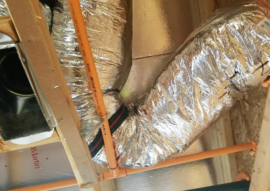
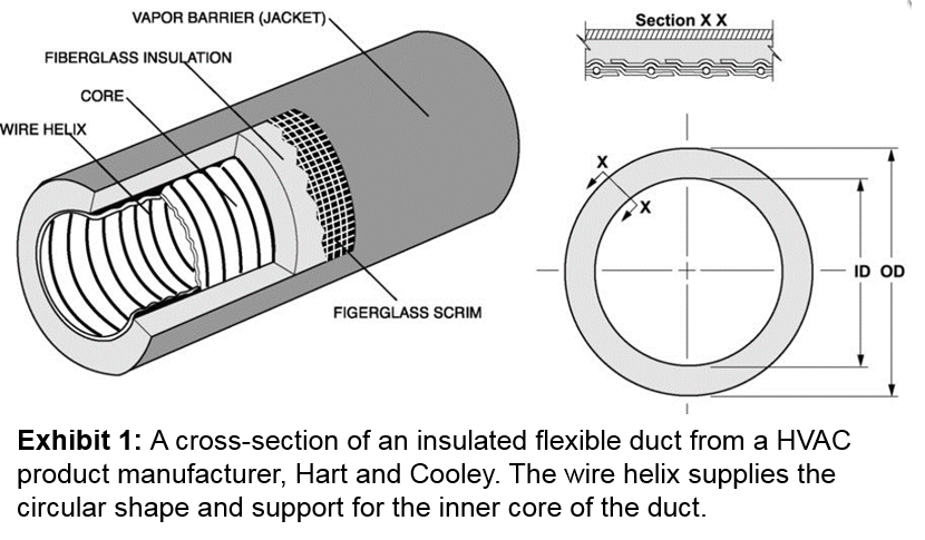
Disruption of air flow at bends in open attic spaces usually occurs where 90-degree changes of direction are sharply installed or where there is only one support, typically located at the bend itself. Other times, this can occur where a straight connection collar at the boot (defined as the transition between the duct inner core and the register) is used in place of a 45 or 90-degree collar connection built into the boot at areas such as terminations near the shallow attic space at the end of a wall. This has the potential to significantly reduce the air flow as it terminates at the register. Once the wire helix (see Exhibit 1) that supports the duct is compromised or bent, the crimped condition will worsen over time as the wire gives in to gravity. The following photos illustrate these typical, incorrect conditions:
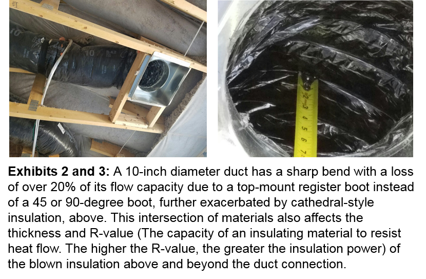
The duct shown in Exhibit 3 (right) was a 10-inch radius duct, however the blown insulation from above compressed the duct to less than 7 inches as it approached the boot. This “bottlenecked” the air flow, as well as created turbulence due to the change of shape in the duct, further reducing the effective air flow.
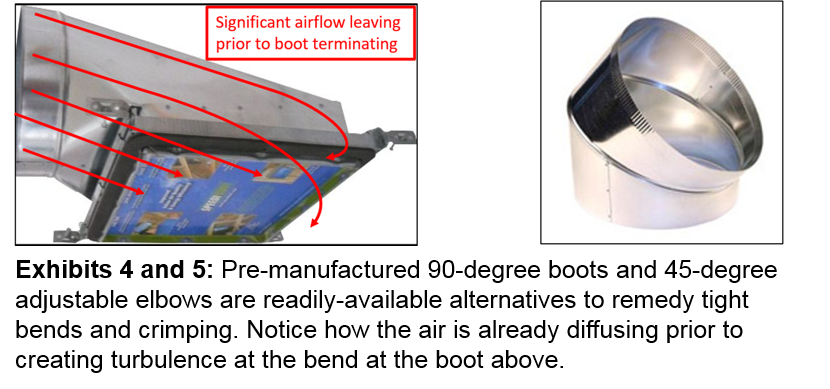
A viable, though slightly less “value-engineered” remedy to this, is to change the boot style or provide a sheet metal elbow to accommodate the limitations of tight locations while maximizing the air flow from the duct and boot to the register, as seen in the examples below:
Below are additional examples of tight bends caused by incorrect installation and incorrectly-selected components:

Industry Solutions to Bends
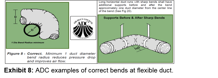
The Air Duct Council (ADC), formerly known as the Air Diffusion Council, is a recognized HVAC industry standards body for the dissemination of flexible duct installation details and performance metrics for efficiency and quality (regularly referenced by government agencies, architects, engineers, manufacturers and HVAC contractors). When it comes to bends, the diameter often changes, resulting in diligence of diameter identification at each bend by the installer. The ADC recommends no tighter than one-duct diameter for bends, with supports before and after bends (See Exhibit 8, below). This practice will reduce the pressure drop issue caused by constriction and turbulence, as well as improve air flow.
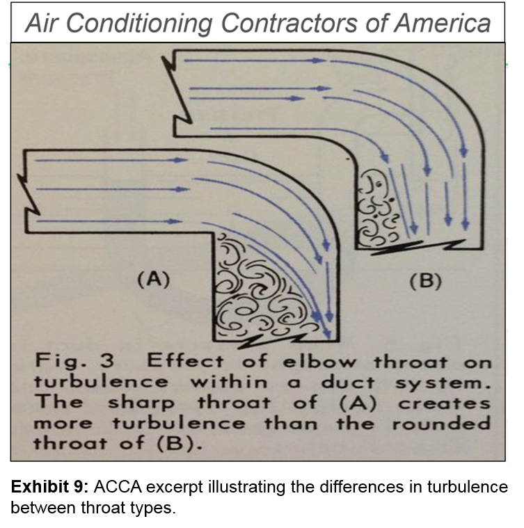
The Air Conditioning Contractors of America (ACCA) is another standardizing association that creates the standards for the design, maintenance, installation, testing and performance of indoor environmental systems. The illustration below shows an excerpt from the ACCA’s Understanding the Friction Chart, where a hard and tight bend creates excessive turbulence, affecting the air flow capacity beyond that point:
Bends at Exhaust Ducts
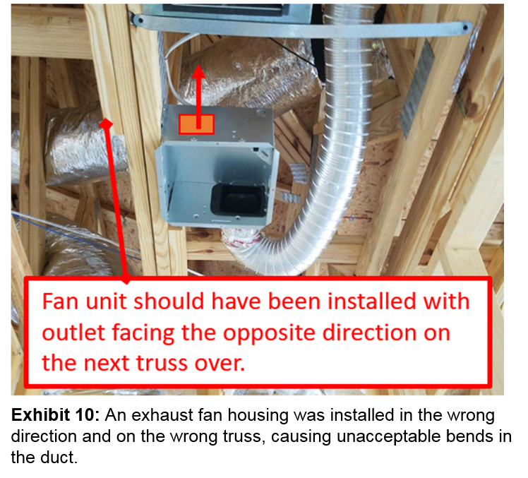
Supply and return ducts are not the only ducts that can experience drops in pressure as a result of tight bends and crimping. Exhaust ducts are governed by the same principles of air movement found for the conditioned air ducts in the ADC guidelines, and experience the same problems resulting from improper installation. A common misconception is that the exhaust fan “can handle” the loss of pressure created when sharp bends are made immediately upon exiting the fan unit. This does not take into account the resulting turbulence that requires excess pressure to fully open the backdraft damper (device that allows airflow in one direction and prevents reverse airflow) and further lessens the adjusted length of run as a consequence. Additionally, exhaust fan units are frequently installed pointed away from the exterior vent termination, creating unnecessary bends (and length, which we will cover later in this article). As mentioned earlier in this article, the improper installation of exhaust fans and duct connections is often the result of the electrical contractor being made responsible for the exhaust fan and housing installation in his/her scope of work due to the fans being an electrically-operated device. While the general location of the fan can often be verified on the plans, the direction of the fan outlet usually cannot (unless specified in the mechanical plans).
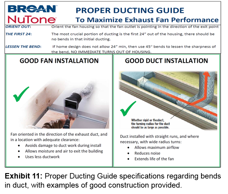
In addition to the industry standards listed so far, most exhaust equipment manufacturers have their own methods of duct installation that coincide with or exceed the industry standards. For example, Broan® and NuTone® specify in the Proper Ducting Guide to Maximize Exhaust Fan Performance to, “Orient the fan housing so that the fan outlet is pointing in the direction of the exit point. The most crucial portion of ducting is the first 24” out of the housing, there should be no bends in that initial ducting.” Unfortunately, the push to provide the timely delivery of a finished product often prevents allotting time for reading any instructions and guidelines provided by specific manufacturers. The photos below illustrate an example of poor installation practices and excerpts from the Proper Ducting Guide:
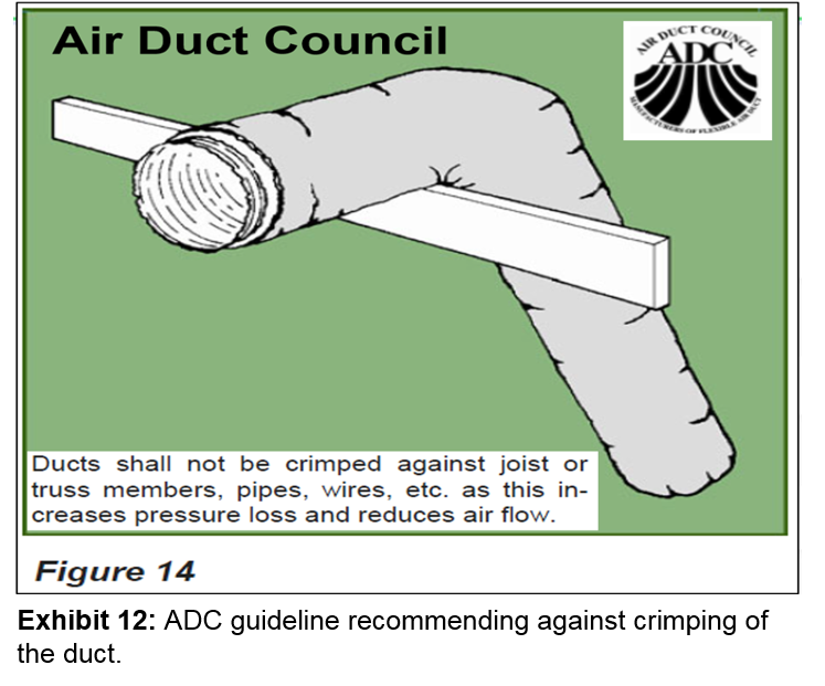
Crimping
Crimping occurs when the duct is bent or otherwise misshapen by trade components such as framing, plumbing, electrical, and even sheet metal HVAC ducts. Not only does this obstruct the flow and increase friction, but it oftentimes damages the ability of the inner core of the duct to maintain the integrity of its shape by bending flat or kinking the wire (helix) that supports the circular shape of the duct. This will further permanently reduce the duct’s air flow capacity over a period of several years before the loss of flow is noticeable. The ADC emphasizes to avoid crimping in its guidelines, “Ducts shall not be crimped against joist or truss members, pipes, wires, etc. as this increases pressure loss and reduces air flow.” as seen below:
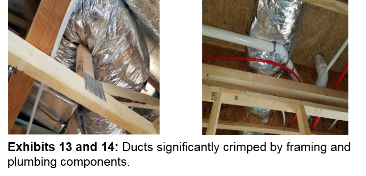
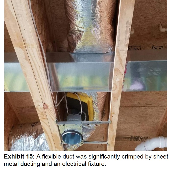
The photos below illustrate a few examples of crimping, which can greatly reduce the ducts’ delivered air flow to the register:
Proper planning for the path and placement of the duct trunks and branches in attics during the mechanical design phase as well as during installation is a recommended practice to avoid crimping. Additional considerations need to be given to all components (in particular, ducts) that are installed in floor joist bays and wall chases. Checking the isometric details in the plans for the locations of HVAC, plumbing, electrical components, and impenetrable framing members and comparing them against each other to ensure enough space and pathways are provided for all components is highly recommended. Amending the location of and/or increasing the depth of joists may be required to meet component needs. Joist bays provide a limited space for multiple components to integrate, including other ducts, and may create significant crimping issues as seen in the photo below:
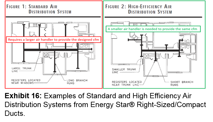
2. Excessive Length
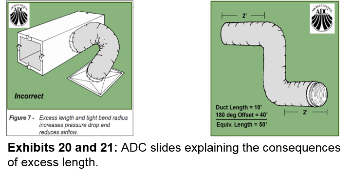
Another common occurrence that increases friction and reduces air flow, is installing an excessive length of flexible duct in both conditioned air and exhaust systems. Duct length should only be long enough to supply conditioned air to the specific location or room, or remove exhaust air to the outside at the first opportunity. Longer ducts can increase the size of the air handler needed to supply the same cubic feet per minute (cfm), or the HVAC system may not be able to supply the designed cfm to all locations. Excessively long supply duct runs were once commonly utilized to place registers at the locations experiencing the greatest conductive exchange of thermal energy with the outside, typically near single-pane windows and doors. These penetrations at exterior wall locations lacked the insulative qualities typically found in modern-day components and recommended installation techniques. For supply and return ducts, short branch duct runs, off a centrally-located trunk duct(s) is the practice recommended by HVAC industry standards. The Environmental Protection Agency (EPA) states in its Energy Star® Right-Sized/Compact Ducts, “The major goal in duct design is to provide proper air distribution throughout a residence. In order to achieve this in an energy-efficient manner, the ducts must be sized and laid out to facilitate air flow and minimize friction, turbulence, and heat loss and gain. The optimal air distribution system has “right-sized” ducts, minimal runs, the smoothest interior surfaces possible, and the least amount of direction and size changes.”
Not only do unnecessarily long runs reduce the air flow due to the increased length, the installers often do not fully extend by pulling these runs taut (stretched or pulled tight), which creates longitudinal compression and results in a loss of air flow due to friction. This compression of the duct increases the friction rate between 2-4 times according to the ADC, as seen below:
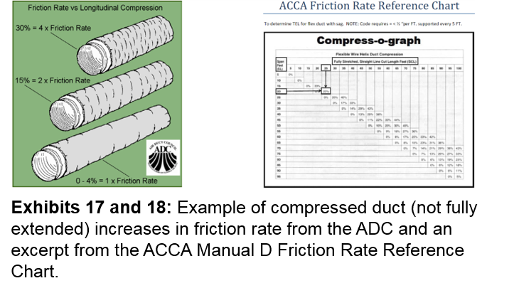
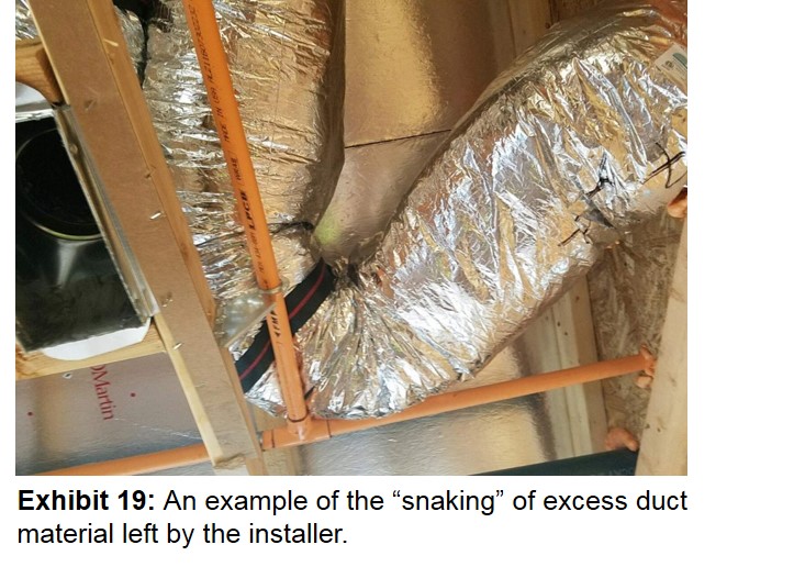
The ADC further states, “Properly take into account duct length, bend losses, sagging or routing expectations, fitting losses, etc. Since all flexible ducts are not alike, use the flexible duct manufacturer’s air friction loss data to size the ducts whenever possible. If no data is available, use the generic flexible duct friction loss chart in ACCA Manual D.” Quite often, the excess duct results in “snaking”; a combination of excessive bends and duct length, which greatly increases the adjusted “equivalent” length of the duct. This often occurs due to running the duct around obstacles as well as failure by the installer to remove excess material, particularly when pre-cut lengths are supplied by the HVAC contractor to their installers, as seen in the example below:
3. Fastening and Sealing
Another overlooked and often misunderstood portion of flexible duct installation is fastening and sealing. Current and past revisions of the Uniform Mechanical Code (UMC) and International Mechanical Code (IMC) state that fasteners and sealant components shall, “comply with the UL 181, and shall be installed in accordance with the Sheet Metal and Air Conditioning Contractor’s National Association (SMACNA) - HVAC Duct Construction Standards-Metal and Flexible” manual.
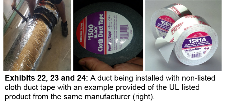
The UL 181A and B/FX listed sealant components need to either be labeled on the tape at a maximum of 6-inch intervals, or in the case of mastic, be labeled on the container. Tape that is UL-listed has the proper adhesion and exceptional shear strength needed to stay in place effectively for the life of the HVAC system. However, it is not unusual to see some HVAC contractors attempt to cut corners financially due to the increased cost of UL-listed tape. In the example below the difference of cost was the reason the unlisted tape was applied:
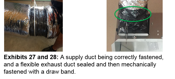
Fasteners for flexible, non-metallic duct are required to be installed by being sealed and then mechanically-fastened with a draw band, as specified by SMACNA in sub-section S3.33, which states, “Non-metallic flexible duct shall be secured to the sleeve or collar with a draw band. If the duct collar exceeds 12” (305 mm) in diameter the draw band must be positioned behind a bead on the metal collar.” These draw bands are best secured in place using a nylon tie tensioning tool.
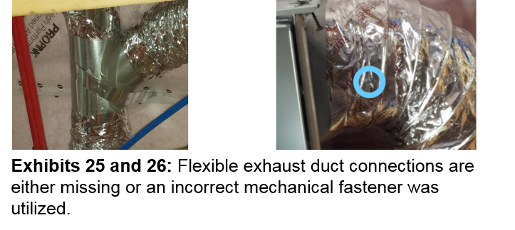
Unfortunately, it is not uncommon for installers to only fasten the outer core of the flexible, conditioned air duct with a draw band, leaving the inner core only sealed and ineffectively connected by tape or mastic. Additionally, flexible exhaust ducts often remain unfastened or incorrectly fastened by a single screw, although governed by the same codes and industry guidelines as supply and return duct. Both conditioned air and exhaust ducts that are not properly sealed or fastened will eventually experience leakage problems.
These problems, already present at an early stage of rough construction, may not become evident during duct-blaster and hood testing at registers and exhaust fans at the final phases of construction - except in the most severe cases. Provision of conditioned and exhaust air flow by oversized mechanical components may allow for an initial window of acceptable testing, but failures may occur years later. The duct will continue to collapse at these points where the structural stability of the duct shape had been originally compromised and in combination with reduced air flow from aging mechanical equipment, as well as ineffective connections separating and leaking. A third-party quality assurance program could easily identify such issues for the builder.
Conclusion
Reliance solely on your trades’ ability and knowledge-base, or on your local jurisdiction’s representatives to evaluate these conditions and every component connection and intersection is not realistic. While the trade contractors you hired may be knowledgeable, most do not verify every installation of their employees with internal quality assurance. Building departments are only responsible for providing observation based on minimum code compliance for a very small sampling.
The best place to start mitigating risk is before you start vertical construction. A technical review of your construction documents for recurring “hot spots,” constructability and performance issues is a highly recommended first step. Another way to minimize that risk and to address such issues prior to them becoming a problem is by contracting with an independent third-party consultation firm to verify consistency in construction practices such as duct placement, sealing, and fastening, as well as providing notification for these observed deficiencies to the parties involved. Quality Built highly recommends all new construction builders and renovators alike to seek an independent assessment of the practices used and components installed at their sites, regardless of who you select to provide these services.
Quality Built’s Technical Plan ReviewTM and Scope of Work Review programs provide our clients with a comprehensive analysis of their project documents; looking for errors, completeness of specifications, conflicting and/or missing details and much more. Quality Built also verifies construction practices for our clients with the time-tested QB Builder Link® Quality Assurance program. We can also supply this invaluable resource to our clients as a customizable internal QA program utilizing the same proprietary app our own inspectors use (supported in IOS and Android mobile device platforms). Furthermore, we can also provide our clients a “big picture” overview of all systems within individual projects and divisions utilizing our Risk Assessment program. Our Forensics team is also able to create a concise report through the onsite analysis of conditions creating concern in both finished and rough products. To verify the efficacy of the HVAC design even further, we also provide HERS field verification for compliance with the standards. A certified Quality Built Home Energy Rating System (HERS®) Rater will visit the site to perform field verification and diagnostic testing to complete the applicable heating and cooling system Certificates of Field Verification and Diagnostic Testing (CF3R). CalGreen Compliance is yet another service we can offer to our California clientele.
About the Author
Remi Kern is a Senior Risk Assessment Specialist, Technical Plan Reviewer and level four Field Consultant at Quality Built.
Remi is highly skilled and accredited in the construction industry. He has been an International Code Council Certified Plans Examiner, Building Inspector, Residential Plumbing and Mechanical Inspector for over ten years. Additionally, he has been a MICRO Certified Mold Remediation Inspector since 2011. Remi is a well-rounded professional, with practical work experience in multiple trades since the late 1980s. He currently performs Quality Built Risk Assessment site consultations nationally, and has been with Quality Built in various capacities since 2005. Remi is an effective communicator and strives to provide superior service to our clients.
You can reach Remi at [email protected]
References
Hart and Cooley - http://www.hartandcooley.com/flex-duct (cross-section image)
Air Diffusion Council - Flexible Duct Performane & Installation Standards, 5th Edition - Chapter 4
Air Diffusion Council - http://www.flexibleduct.org/ADC_Info.asp
The Air Conditioning Contractors of America (ACCA) - Understanding the Friction Chart Fig. 3
The Air Conditioning Contractors of America (ACCA) - Manual D (Residential Duct Design)
The Air Conditioning Contractors of America (ACCA) - http://www.acca.org/about-acca
Broan® and NuTone® - Proper Ducting Guide To Maximize Exhaust Fan Performance
Environmental Protection Agency (EPA) - Energy Star® Right-Sized/Compact Ducts
Uniform Mechanical Code
International Mechanical Code